Reading and Mpving Encoder Motors With Ez Robot
If Colin is going to create a map of the space he's in, he needs to exist able to find the distance between objects in the space. If he'southward going to accurately command his own motion, he needs to exist able to control the speed of his motors. For both of these things he needs information virtually how far and how fast his motors are turning. To give Colin that information I added encoders to his motors. Encoders are special sensors that rails both how far his motor shafts have turned, and in what direction.
The following tutorial will discuss how to use shaft encoders with DC motors. First I'll discuss the principles the encoders work on, so I'll show you how to wire up an encoder and verify that it's working. This tutorial owes a large dept to the Penn State Robotics Order Wiki, which has an excellent page on bicycle encoders.
For this tutorial I'll be using these magnetic encoders from Pololu. They are great for use with an Arduino because their output is a prissy, easy to read, digital square wave. Pololu also offers an analog optical encoder, only to reliably read its output you need to apply a ADC (analog to digital converter). Also, the optical encoder is susceptible to interference from bright lite. So magnetic encoders are easier to utilize and more than reliable for our purposes.
Encoder Principles
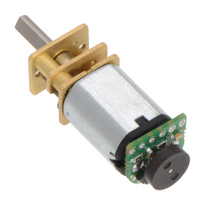
Pololu'south shaft encoders add together a 6 pole magnetic disc to the shaft of the motor, likewise as two Hall effect sensors. As the motor turns the disc rotates past the sensors. Each time a magnetic pole passes a sensor, the encoder outputs a digital pulse, also called a "tick." The encoder setup is pictured below.

motor encoder installation example (from pololu.com)
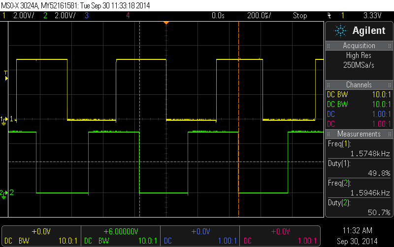
The encoder has two outputs, i for each Hall effect sensor. The sensors are separated past 90 degrees. This means the foursquare wave outputs of the sensors are xc degrees out of phase. This is called a quadrature output. The picture show below (taken from Pololu'due south website) shows the typical output of an encoder.

Output of an encoder (from pololu.com)
Why is information technology important that the output pulses are 90 degrees out of phase? This allows united states of america to determine both the magnitude and thedirectionof the motor'south rotation. If output A is ahead of output B, and then the motor is turning forward. If output A is backside B, the motor is turning backward. Pretty cool, right?
Encoder Setup and Wiring
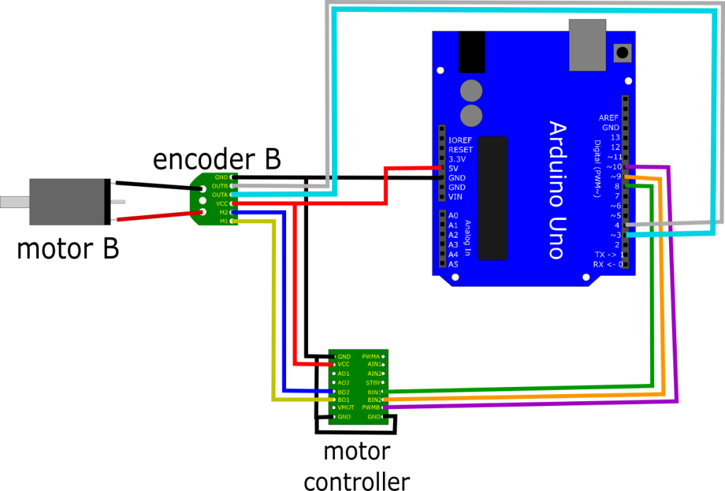
Wiring upwards the encoders is pretty elementary. See the diagram below for details on wiring upward the encoder for motor B, and repeat for motor A.

wiring for a single motor and encoder
Note that the encoder pin OUTA needs to exist connected to a hardware interrupt pin (digital pivot 2 or 3 on an Arduino Duemilanove or Uno). For this example it'south non really necessary to use hardware interrupts but if you don't your Arduino won't be able to exercise anything merely track the encoder. Interrupts allow your Arduino to keep rails of the encoders while it's running some other program.
It's as well important when installing your motors to not mountain them too close to each other. If your motors are mounted back-to-dorsum, the magnetic encoder wheels volition interfere with each other. I initially had only well-nigh 5mm between the two encoder wheels. The magnets in the encoder wheels linked with each other and made it impossible for the two motors to turn at different speeds. Keeping the encoder wheels at least 20mm apart seems to avoid any interference bug.
Hardware Interrupts
It's pretty easy to write a program that just counts the number of ticks. But if, for some reason, you lot want your program to do anything only rail the encoders you need to use hardware interrupts.
With hardware interrupts your main program runs until the land of ane of the Arduino's interrupt pins changes. Then the main program is stopped, a special interrupt method is run, and then the main program is resumed. For example, an obstacle avoidance routine tin run in the foreground only if 1 of the interrupt pins changes from low to high the position or speed of the motor tin can be updated in the interrupt method.
Because the main program is stopped when the interrupt method is triggered, the length of the interrupt method should exist kept as short as possible. If the interrupt method is too long, then the Arduino will spend all of its time running the interrupt method and it will never actually run the main program.
For more details on hardware interrupts check out this page on the Arduino playground.
Case Sketch
The sketch below simply prints the values of the ii count variables. When the motors are moved, the encoder output triggers the appropriate encoder outcome method. The encoder effect methods either increment or decrement the count variables, keeping track of the number of ticks from each encoder. If the motor is turned forward, the count is incremented and it is decremented if the motor is turned backward.
The motors need to be moved manually for this sketch. They won't motion themselves. We volition aggrandize this to do simple motor speed control in a afterward tutorial.
Nosotros'll define motor direction somewhat arbitrarily: If RH_ENCODER_A is HIGH and RH_ENCODER_B is Low so the motor is turning forward. If RH_ENCODER_A is Loftier and RH_ENCODER_B is likewise Loftier, then the motor is turning backward. You lot tin can swap the wires for ENCODER_A and ENCODER_B to alter the direction if required.
/* * Encoder case sketch * by Andrew Kramer * 1/1/2016 * * Records encoder ticks for each wheel * and prints the number of ticks for * each encoder every 500ms * */ // pins for the encoder inputs #define RH_ENCODER_A iii #define RH_ENCODER_B 5 #define LH_ENCODER_A 2 #define LH_ENCODER_B 4 // variables to store the number of encoder pulses // for each motor volatile unsigned long leftCount = 0; volatile unsigned long rightCount = 0; void setup() { pinMode(LH_ENCODER_A, INPUT); pinMode(LH_ENCODER_B, INPUT); pinMode(RH_ENCODER_A, INPUT); pinMode(RH_ENCODER_B, INPUT); // initialize hardware interrupts attachInterrupt(0, leftEncoderEvent, Change); attachInterrupt(1, rightEncoderEvent, CHANGE); Serial.begin(9600); } void loop() { Series.print("Right Count: "); Serial.println(rightCount); Serial.print("Left Count: "); Serial.println(leftCount); Serial.println(); delay(500); } // encoder effect for the interrupt telephone call void leftEncoderEvent() { if (digitalRead(LH_ENCODER_A) == HIGH) { if (digitalRead(LH_ENCODER_B) == LOW) { leftCount++; } else { leftCount--; } } else { if (digitalRead(LH_ENCODER_B) == LOW) { leftCount--; } else { leftCount++; } } } // encoder event for the interrupt call void rightEncoderEvent() { if (digitalRead(RH_ENCODER_A) == HIGH) { if (digitalRead(RH_ENCODER_B) == Low) { rightCount++; } else { rightCount--; } } else { if (digitalRead(RH_ENCODER_B) == LOW) { rightCount--; } else { rightCount++; } } } That's all for today. In my next mail I'll have what we learned nearly using encoders with hardware interrupts and incorporate that into a simple speed control routine. Afterward that nosotros can dive into real PID control!
Source: http://andrewjkramer.net/motor-encoders-arduino/
0 Response to "Reading and Mpving Encoder Motors With Ez Robot"
Post a Comment